Date: February 9nd, 2022
Objectives
- Figure out the wiring between the TOF sensors, IMU, and Artemis Nano and solder the connections
- Get the sensors functioning/Test the sensors
Components
- 1 x SparkFun RedBoard Artemis Nano
- 1 x USB-C to USB-C cable
- 2 x VL53L1X Time of Flight sensors
- 1 x ICM-20948 Inertial Measurement Unit sensor
- Stranded wires
- Soldering iron + solder
Procedure
- I installed the SparkFun VL53L1X Time of Flight Sensor library & the SparkFun 9DOF IMU Breakout ICM 20948 Arduino Library in the Arduino IDE.
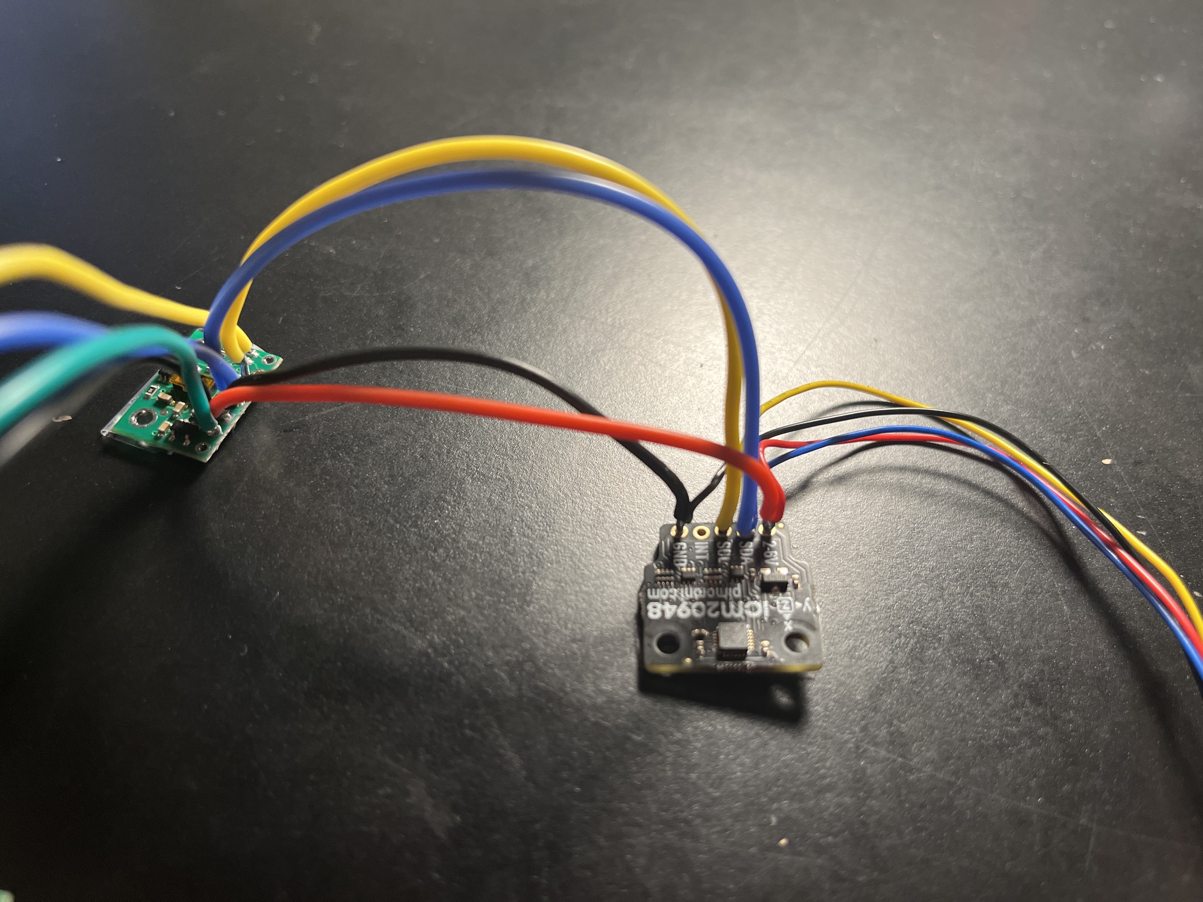
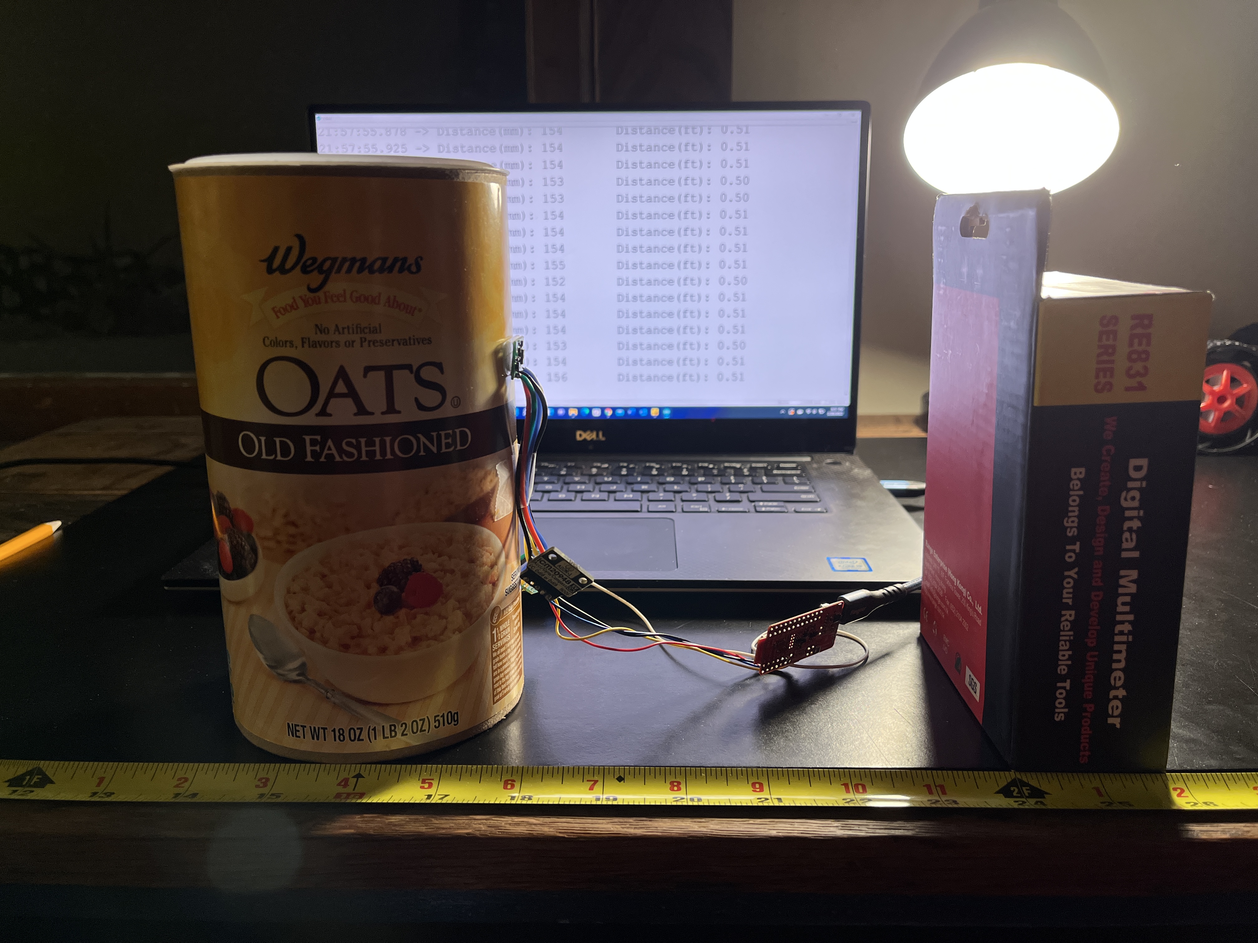
- Thinking about the sensor positioning on the RC car, I did all the soldering first.
- I used the QWIIC-to-cable connecter from the Artemis Nano to the IMU
- Then I daisy chained the first TOF sensor to the IMU
- Finally, I daisy chained the first TOF to the second TOF
- The second TOF has the XSHUT pit connect to the Artemis nano pin A3.
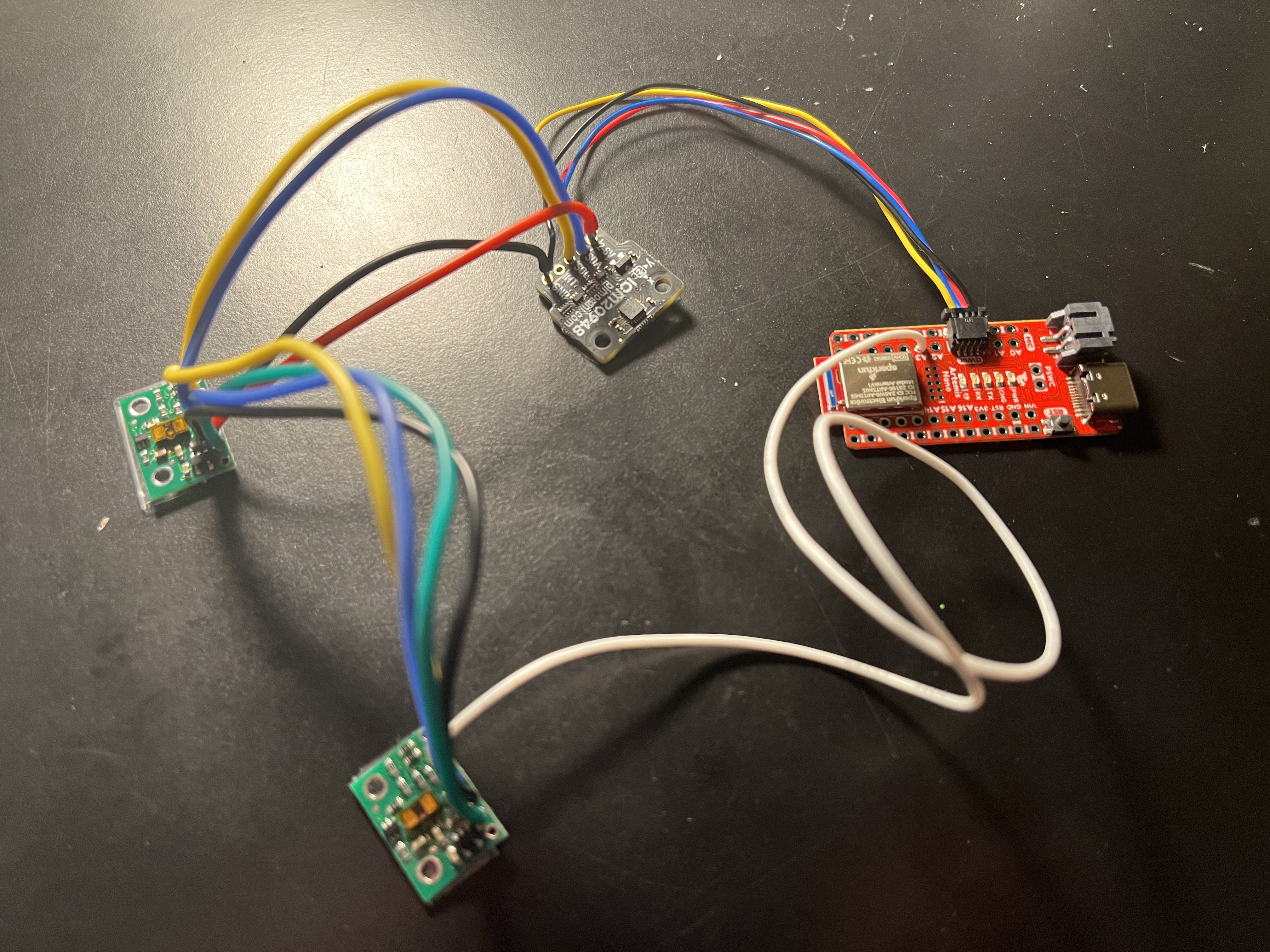
- I uploaded File->Examples->Apollo3->Example05_Wire_I2C
- VL53L1X I2C device address: 0x52 = 82 in decimal = 0b1010010 in binary
- ICM-20948 I2C address: AD0 = 0 -> 0x68 = 104 in decimal = 0b1101000 in binary
- AD0_VAL is 1 by default unless the ADR jumper is connected. Connecting the I2C ADR jumper changes the default address of the IMU and AD0_VAL becomes 0. In this case the internal jumper is connected, so AD0_VAL should be 0.
- Becuase I connected the IMU first, I was able to properly detect its address before I connected the 2 TOF sensors
I ran into the issue with printing the addresses when all the sensors are connected.
- I used .setDistanceModeShort(), the short distance mode
- Short distance mode is less affected by the ambient light conditions, but its maximum ranging distance is more limited
VL53L1X TOF Sensor
Testing Setup
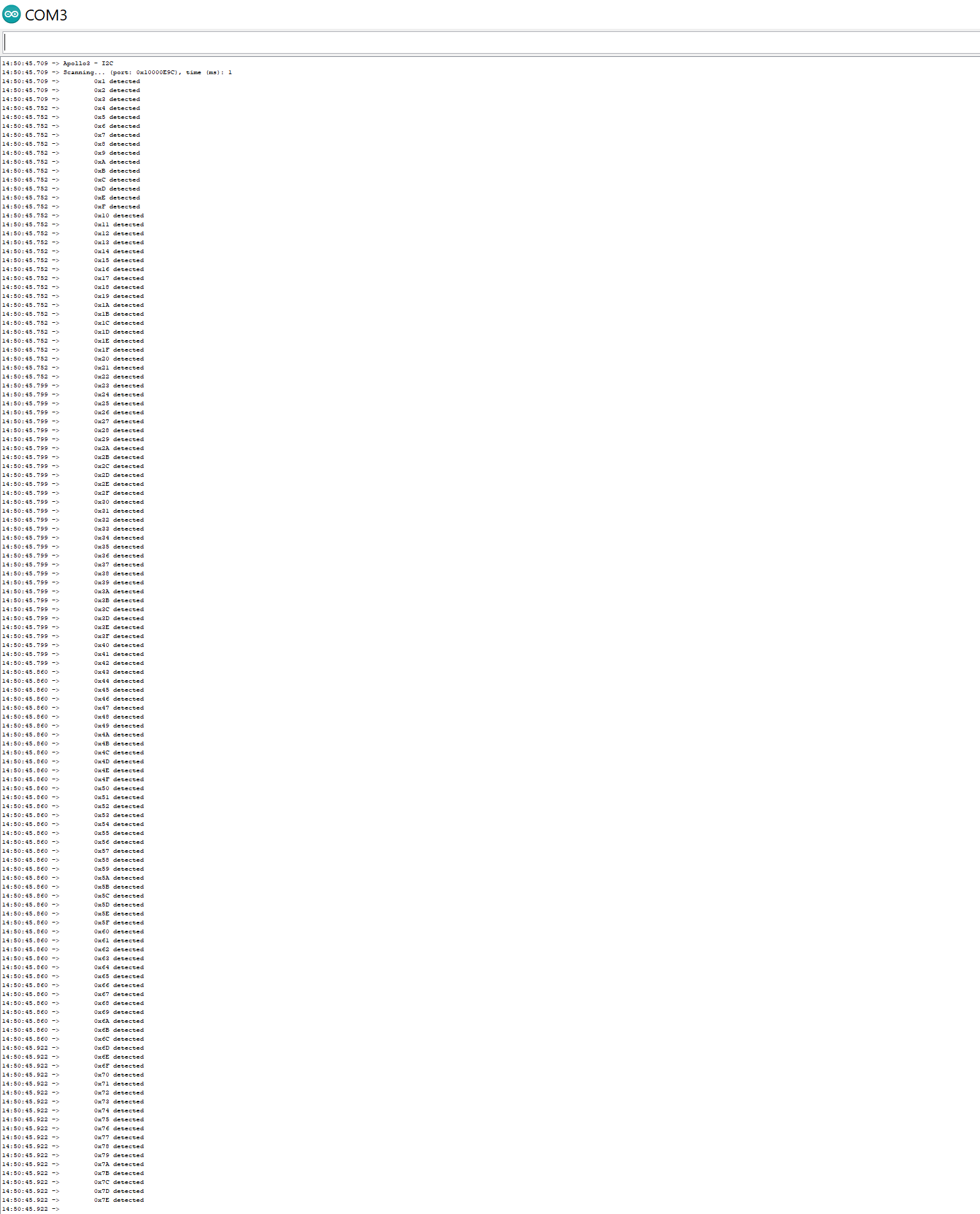
You can see the TOF senor is half a foot from the black and red box, and in the background the Serial Monitor is printing the distance is 0.50 ft.
- I uploaded File->Examples->SparkFun VL53L1X 4m Laser Distance Sensor->Example1_ReadDistance
- I changed the sketch to also get the ranging time and the presecribed inter-measurement period
- I removed the vacuum tape from the sensor before taking any measurements
- The TOF was set at the end of the tape measure, and I moved the black and red box towards and away from the sensor in 1 inch increments
- 3 trials were performed
Range, accuracy, repeatability
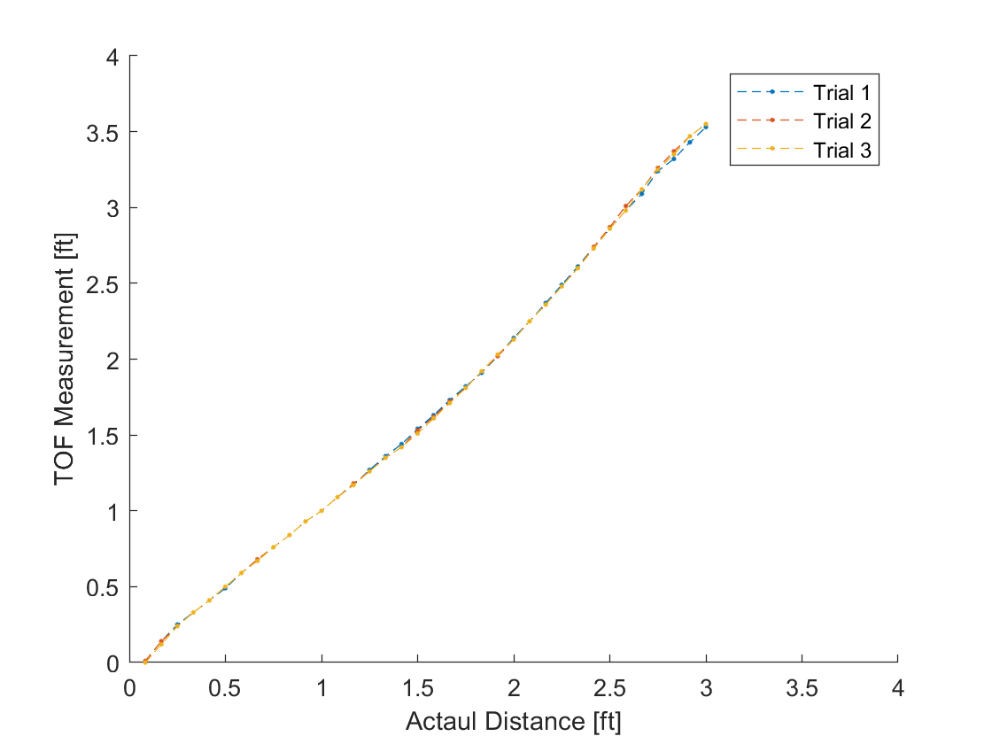
- The sensor has good repeatability even in the short distance mode (where the timing budget can be decreased more than in the other modes)
- The data is linear between 0.5 feet and 2 feet which means the expected and actual measurements match very well. In this section the measurements are accurate.
- The x-offset of the graph shows the minimum discernable distance in practice is around an inch
- I found the maximum distance measurable in short distance mode to be 7.71 ft (2.35 m) when the actual distance was 8 ft. After going past 8ft, the measured distance registered as 0.00 ft. However, the TOF sensor is not accurate at this distance.
Ranging time
- I used the .getIntermeasurementPeriod() method
- The specified inter-measurement period (in milliseconds) determines how frequently the sensor takes a measurement
- If it’s shorter than the timing budget, the sensor will start a new measurement as soon as the previous one finishes
- According to the datasheet, the default timing budget is 100 ms
- It’s possible to decrease it to 20 ms only in short distance mode, but this affects repeatability
- Increasing the timing budget increases the maximum range the device can measure and improves the repeatability error, but the power consumption increases as well
- I also manually calculated the elapsed time using millis() and taking the difference of the time just after ranging starts and just after ranging stops
As I take measurements at different distances, the calculated time and period remain constant
Different colors and textures
I used my hand which has an irregular shape, a lamp to change the amount of ambient light, and a bright green notebook which has a different surface texture and color to test the TOF sensor. I didn’t see any significant changes to the results.
ICM 20948 IMU Sensor
- I uploaded File -> Examples -> SparkFun 9DoF IMU Breakout – ICM 20948 – Arduino Library -> Arduino -> Example1_Basics
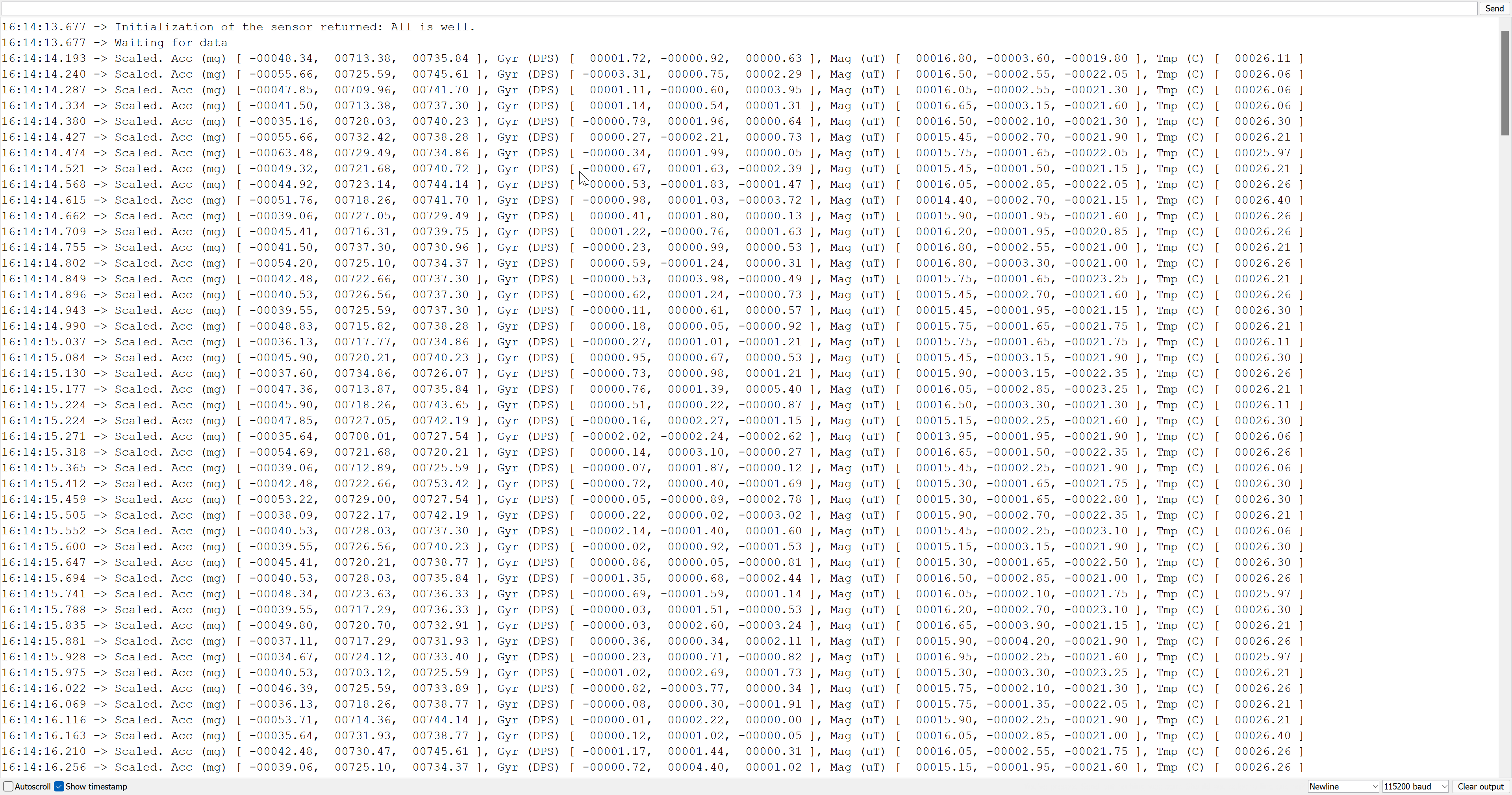
- Next, I changed the sketch to only output the data I needed for each test
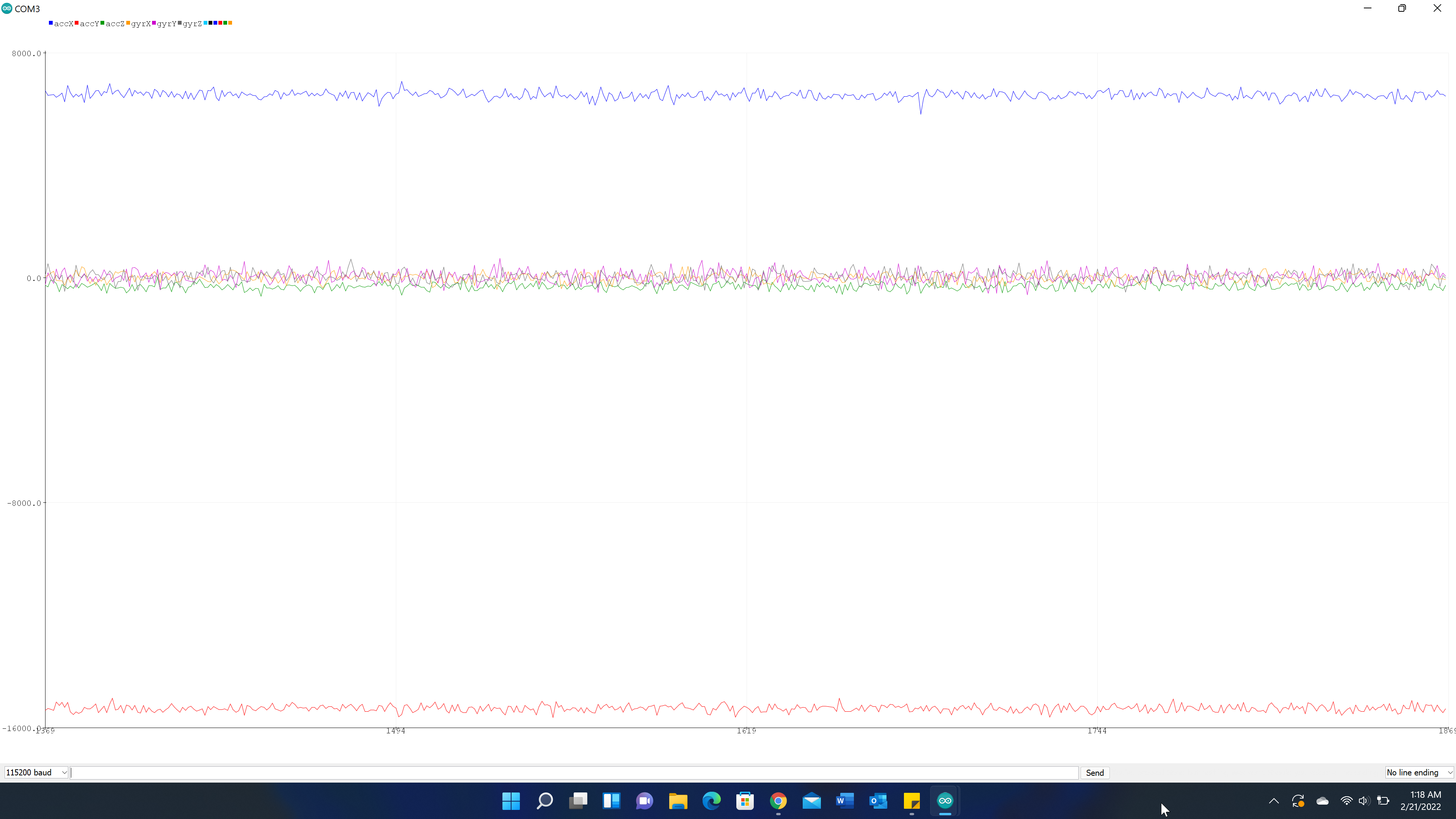
- I also looked at the difference between the raw IMU data vs the scaled IMU data.
Raw IMU Data
Scaled IMU Data
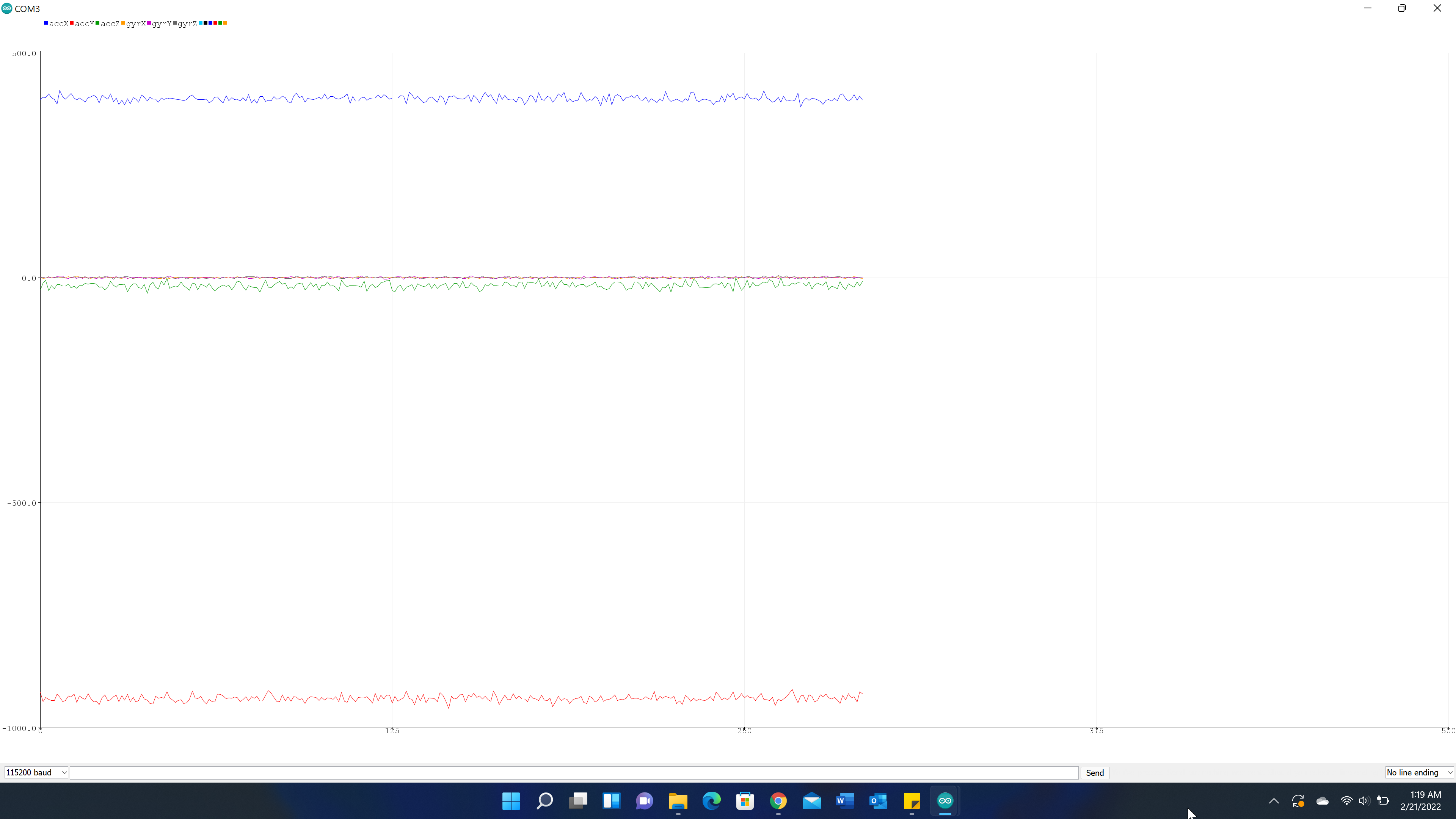
- The scaled data looks less noisy
This video shows the x, y, and z components from the accelerometer and gyroscope.
The accleration ouputs are in units of milli-g’s. That is why the y acceleration (the green line) is offset from zero by 1000. You can see the 6 different line plots responsd appropriately to the movement of the sensor.
The accelerometer is pretty accurate. Both the pitch and roll changed by -90 and +90 degrees according to the tilting of the sensor.
Frequency Response
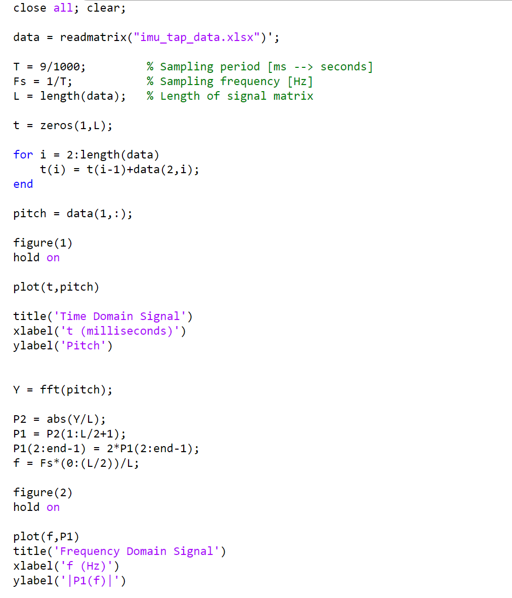
I saved the data from the Serial Monitor and used the following MATLAB script to plot the time and frequency domains.
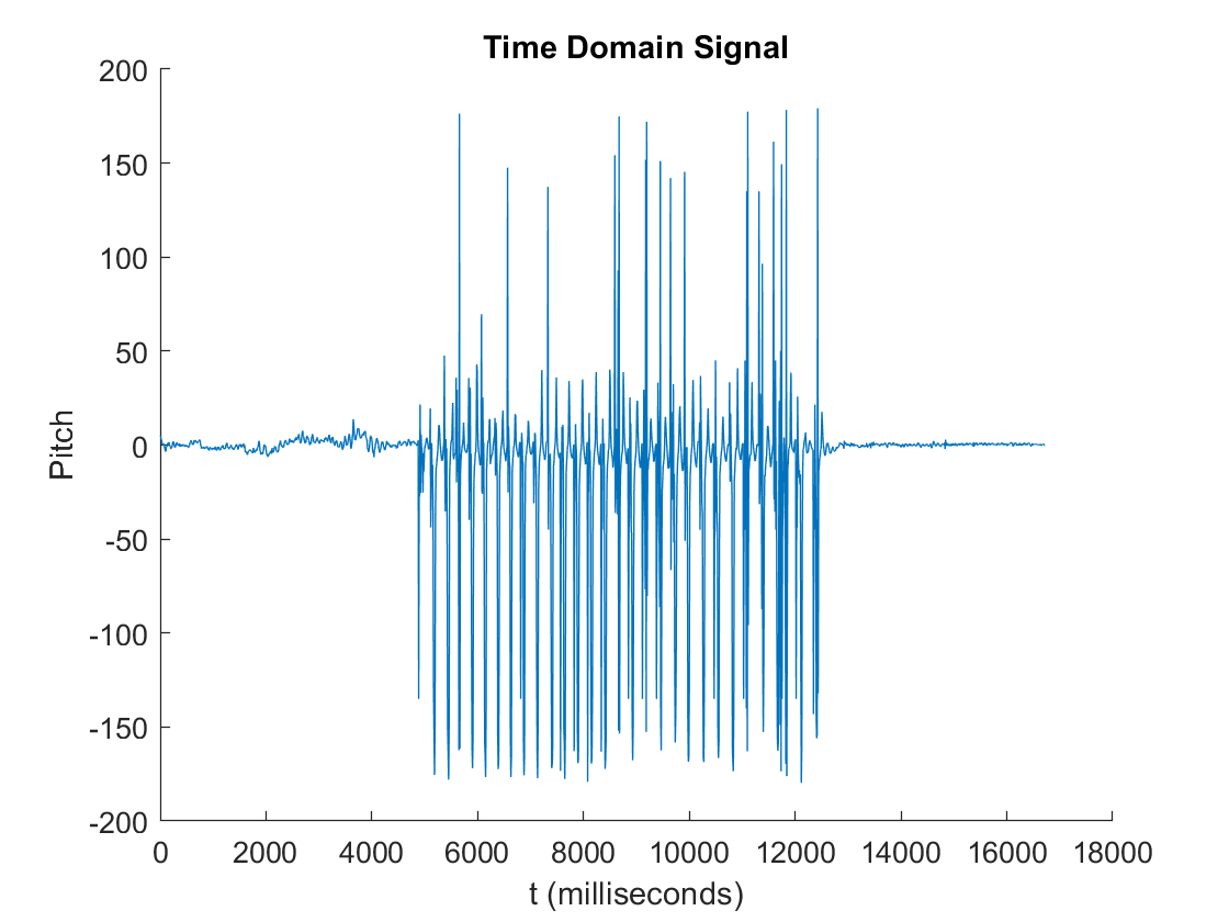
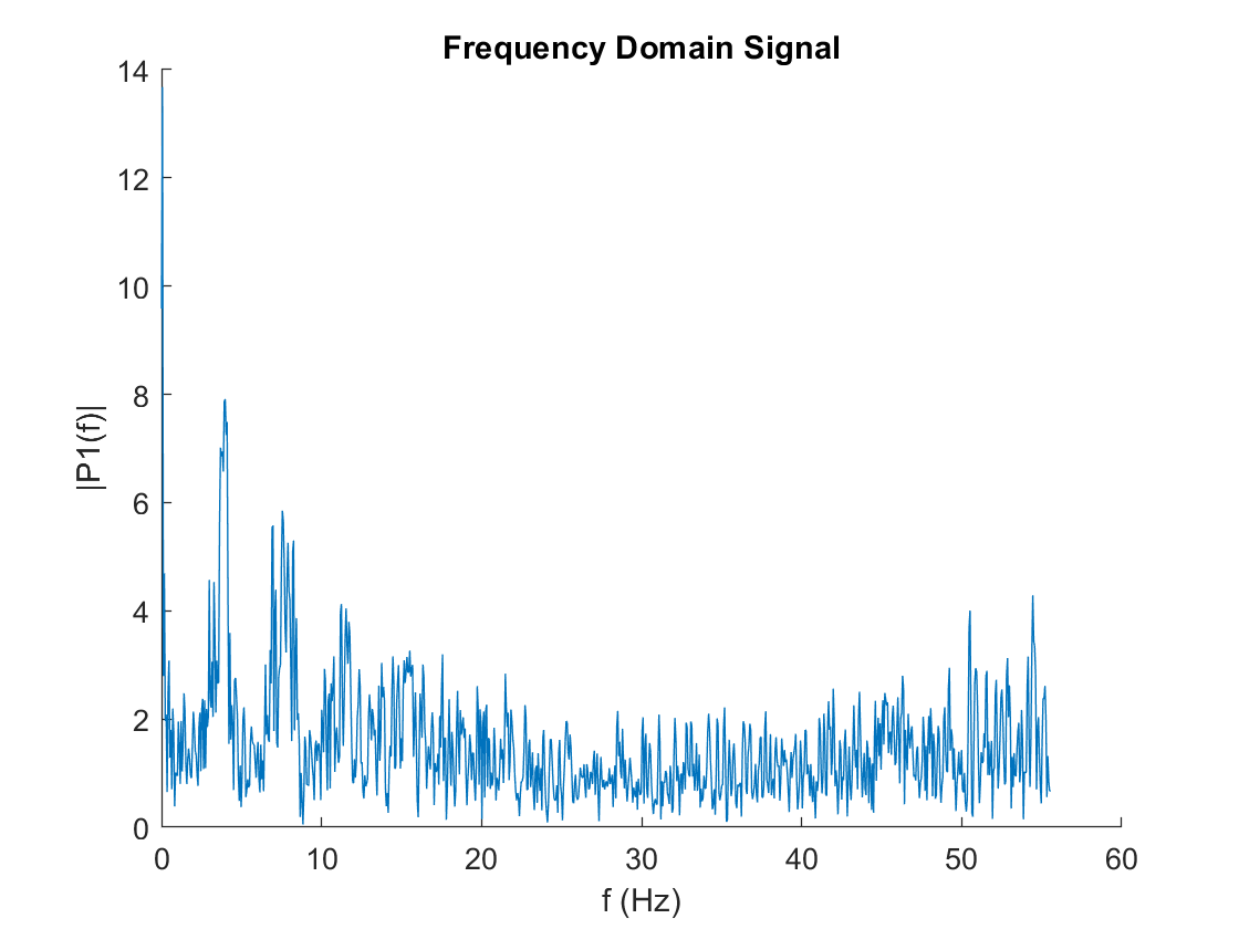
I was tapping at about 240 beats per minute (bpm) which is equivalent to about 4 Hz. Around 4 Hz there is a peak with an amplitude of 8. The sensor seems to be pretty noisy. I performed the following calculation to determine the Low Pass Filter parameters.
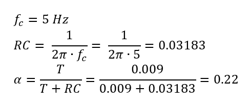
I used this alpha in my code to find the pitch. Increasing f_c, the cutoff frequency, increases RC which in turn increases the value of alpha and makes a more aggressive low pass filter.
Implementation of the Low Pass Filter
The low pass filter smooths out the data by removing some of the noise. I don’t see significant lag with my filter. It follows the accelerometer pitch well.
Here are two close up images to clearly see how the low pass filter is changing the output:
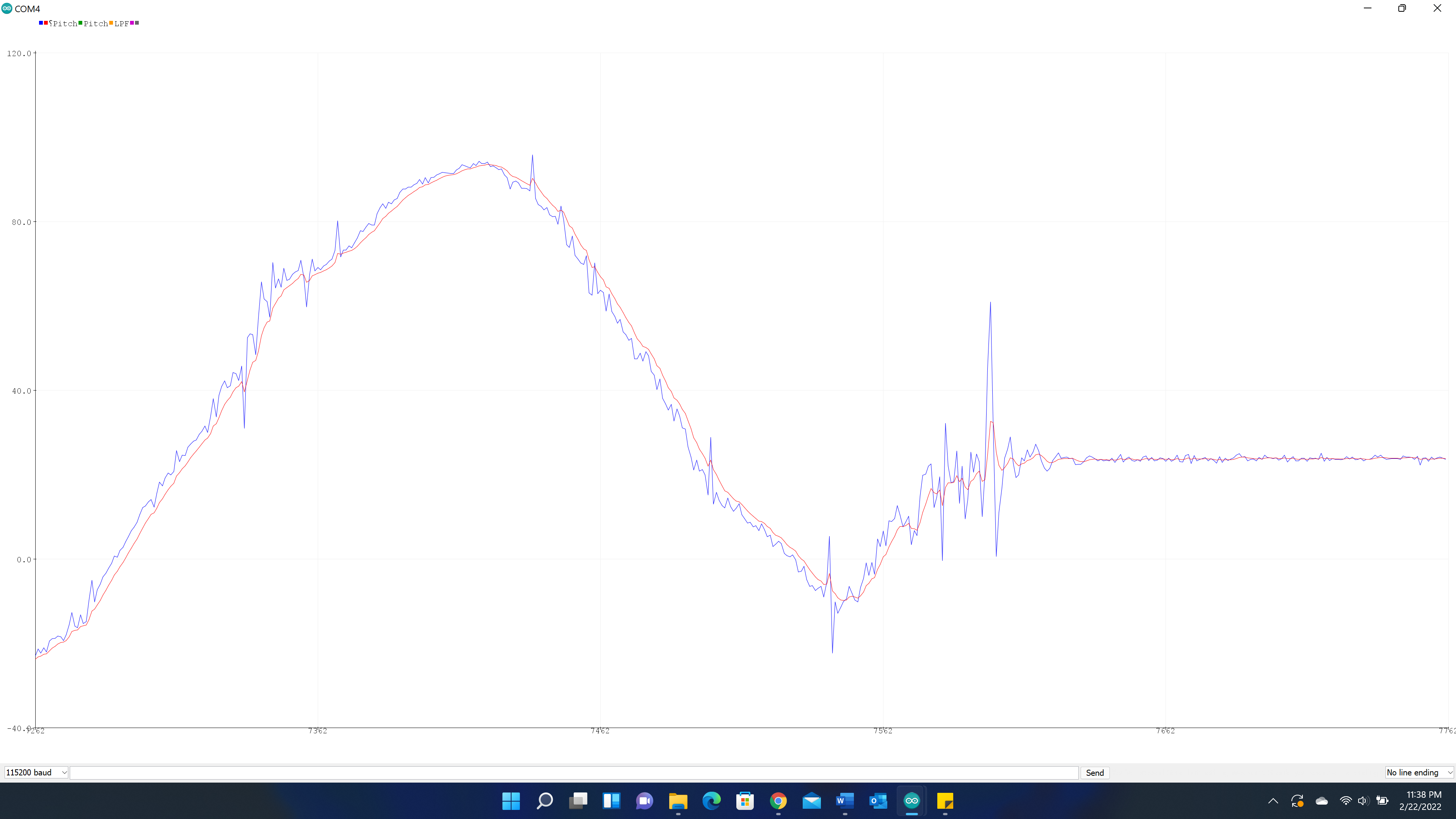
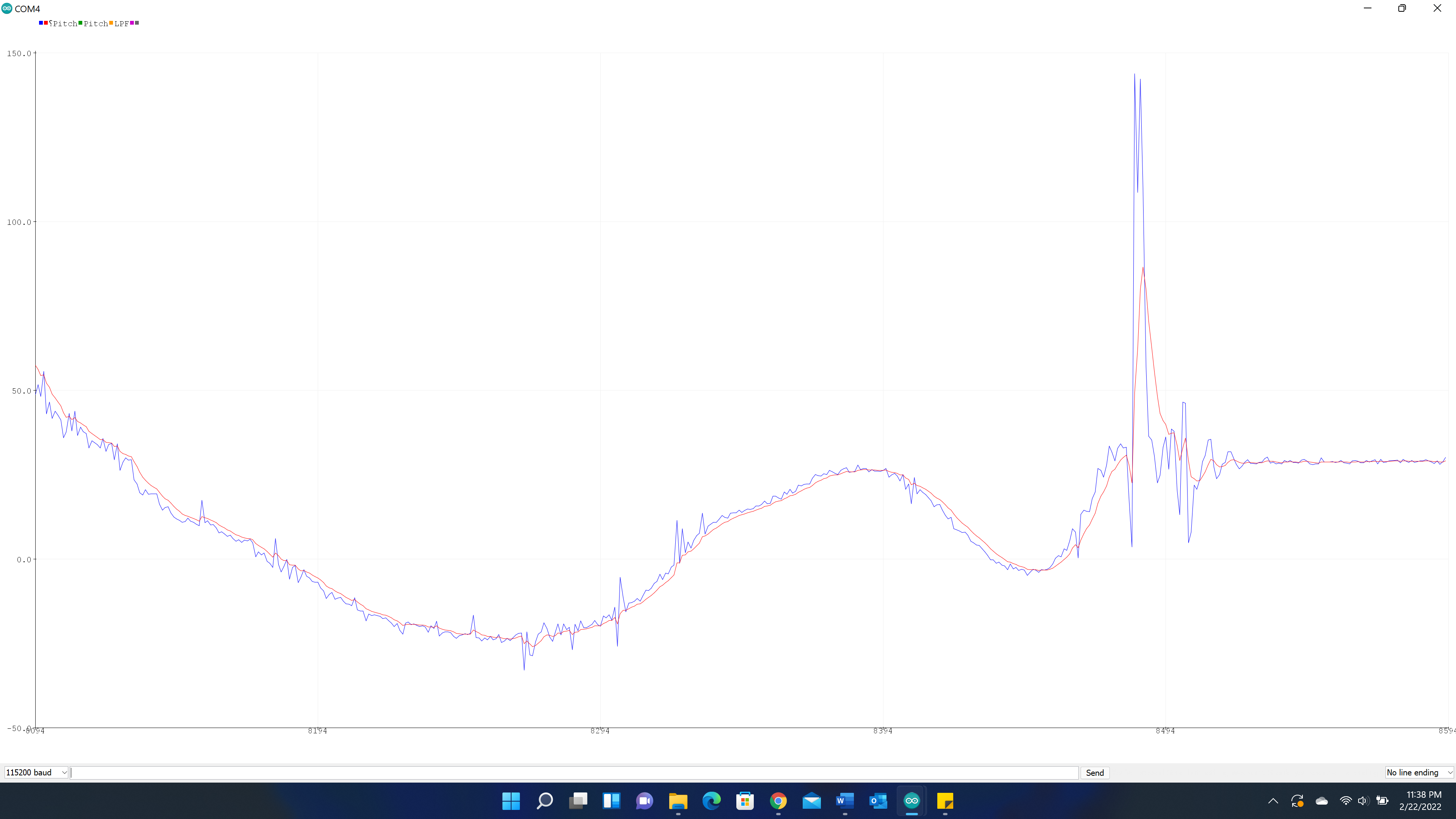 There is less jaggedness due to noise and less response to big jumps.
Gyroscope
The output values are all comparable. The pitches all follow each other. The same goes for the rolls. The values for yaw are reasonable as well.
Code
This is my code for the TOF tests:
#include <ComponentObject.h>
#include <RangeSensor.h>
#include <SparkFun_VL53L1X.h>
#include <vl53l1x_class.h>
#include <vl53l1_error_codes.h>
#include <Wire.h>
#include "SparkFun_VL53L1X.h" //Click here to get the library: http://librarymanager/All#SparkFun_VL53L1X

#define SHUTDOWN_PIN A3

SFEVL53L1X distanceSensor;

//Uncomment the following line to use the optional shutdown and interrupt pins.
SFEVL53L1X distanceSensor2(Wire, SHUTDOWN_PIN);

//global variables available anywhere in the program
unsigned long startMillis;
unsigned long currentMillis;
unsigned long diff;

void setup(void)
{
  Wire.begin();

  Serial.begin(115200);
  Serial.println("VL53L1X Qwiic Test");

  if (distanceSensor.begin() != 0) //Begin returns 0 on a good init
  {
    Serial.println("Sensor failed to begin. Please check wiring. Freezing...");
    while (1)
      ;
  }
  Serial.println("Sensor online!");

  pinMode(SHUTDOWN_PIN, OUTPUT);
  digitalWrite(SHUTDOWN_PIN, LOW);

  distanceSensor.setDistanceModeShort();
}

void loop(void)
{
  distanceSensor.startRanging(); //Write configuration bytes to initiate measurement
  startMillis = millis();
  while (!distanceSensor.checkForDataReady())
  {
    delay(1);
  }
  int distance = distanceSensor.getDistance(); //Get the result of the measurement from the sensor
  distanceSensor.clearInterrupt();
  distanceSensor.stopRanging();
  currentMillis = millis();
  diff = currentMillis-startMillis;

  Serial.print("Distance(mm): ");
  Serial.print(distance);

  float distanceInches = distance * 0.0393701;
  float distanceFeet = distanceInches / 12.0;

  Serial.print("\tDistance(ft): ");
  Serial.print(distanceFeet, 2);

  //Serial.print("\tRanging Time(ms): ");
  //Serial.print(diff);


  Serial.print("\tPeriod (ms): ");
  Serial.print(distanceSensor.getIntermeasurementPeriod());

  Serial.println();
}
This is my code for all the IMU tests:
#include "ICM_20948.h" // Click here to get the library: http://librarymanager/All#SparkFun_ICM_20948_IMU
#include <Wire.h>
#include <math.h>

#define AD0_VAL 0

ICM_20948_I2C myICM; // Create an ICM_20948_I2C object

// All my variables here
unsigned long past = 0;
double pitch_a_LPF[] = {0,0};
const int n = 1;
double dt = 0;
unsigned long prev = 0;
double pitch_g = 0;
double roll_g = 0;
double yaw_g = 0;
double pitch = 0;
double roll = 0;


void setup() {
  // put your setup code here, to run once:
  Wire.begin();
  Serial.begin(115200);
  myICM.begin(Wire, AD0_VAL);

  //Serial.print("accX, accY, accZ, gyrX, gyrY, gyrZ "); // Plotter Legend
  //Serial.print("Pitch, Roll ");
  //Serial.print("Pitch");
  //Serial.print("Pitch, Pitch LPF ");
  //Serial.print("Pitch, Roll, Yaw ");
  //Serial.print("Pitch(A), Roll(A), Pitch_LPF(A), Pitch(G), Roll(G), Yaw(G) ");
  Serial.print("Pitch(A), Roll(A), Pitch(G), Roll(G), Pitch_co, Roll_co ");
}

void loop() {
  // put your main code here, to run repeatedly:
  if (myICM.dataReady())
  {
    myICM.getAGMT(); // The values are only updated when you call 'getAGMT'
    double period = millis()-past;
    past = millis();

    // PART 1 - Acc test

    Serial.print( myICM.accX() );
    Serial.print(", ");
    Serial.print( myICM.accY() );
    Serial.print(", ");
    Serial.print( myICM.accZ() );
    Serial.print(", ");
    Serial.print( myICM.gyrX() );
    Serial.print(", ");
    Serial.print( myICM.gyrY() );
    Serial.print(", ");
    Serial.print( myICM.gyrZ() );


    // PART 2 - Acc Pitch and Roll

    double pitch_a = atan2(myICM.accX(), myICM.accZ())*180/M_PI;
    double roll_a = atan2(myICM.accY(), myICM.accZ())*180/M_PI;

    Serial.print(pitch_a);
    Serial.print(", ");
    Serial.print(roll_a);
    Serial.print(", ");


    // PART 3 - Acc FFT tapping test

    double pitch_a = atan2(myICM.accX(), myICM.accZ())*180/M_PI;

    Serial.print(pitch_a);
    Serial.print(" ");
    Serial.print(period);


    // PART 4 - Acc Pitch & LPF Pitch

    double pitch_a = atan2(myICM.accX(), myICM.accZ())*180/M_PI;

    Serial.print(pitch_a);
    Serial.print(", ");

    const float a = 0.22;
    pitch_a_LPF[n] = a*pitch_a + (1-a)*pitch_a_LPF[n-1];
    pitch_a_LPF[n-1] = pitch_a_LPF[n];
    Serial.print(pitch_a_LPF[n]);
    Serial.print(", ");


    // PART 5 - Gyr

    dt = (micros()-prev)/1000000.0;
    prev = micros();
    pitch_g = pitch_g - myICM.gyrY()*dt;
    roll_g = roll_g + myICM.gyrX()*dt;
    //yaw_g = yaw_g + myICM.gyrZ()*dt;

    Serial.print(pitch_g);
    Serial.print(", ");
    Serial.print(roll_g);
    Serial.print(", ");
    //Serial.print(yaw_g);

    // PART 6 - Complimentary Filter
    double pitch = (pitch - myICM.gyrY()*dt)*0.9 + pitch_a*0.1;
    double roll = (roll + myICM.gyrX()*dt)*0.9 + roll_a*0.1;

    Serial.print(pitch);
    Serial.print(", ");
    Serial.print(roll);


    Serial.println();
  }

}
